


CFD analysis of thermal energy storage (TES) tanks for data centers
In a data center, stored cooling has to be there when it's called on. CFD analysis predicts thermocline behavior and usable capacity across the full operating range. The CFD provides fabricators with confirmation that the design will meet the required rating before the steel is cut, owners get performance guarantees backed by evidence, and retrofit teams learn whether an existing tank will perform under new conditions before the live system is at risk.
- Transient CFD for the full discharge duration
- Outlet temperature vs time, against your limit
- Typical turnaround: a few days
What the analysis answers
At your flow, temperatures and allowable rise
- Time to limit
- Seconds until the outlet temperature reaches the allowable rise.
- Usable volume
- Gallons delivered within the limit, against the volume the specification requires.
- Thermocline
- Its position and thickness over time, and what is thickening it.
- Internals and inlet
- Baffle design and count, spacing and open area; diffuser design; nozzle velocity.
- Charge and recharge
- How fast the tank recovers after the chillers restart or after other load-shift events.
- Verdict
- Meets the specification, or the design change that makes it meet it.
Discharge simulation
How perforated baffles extend thermal ride-through
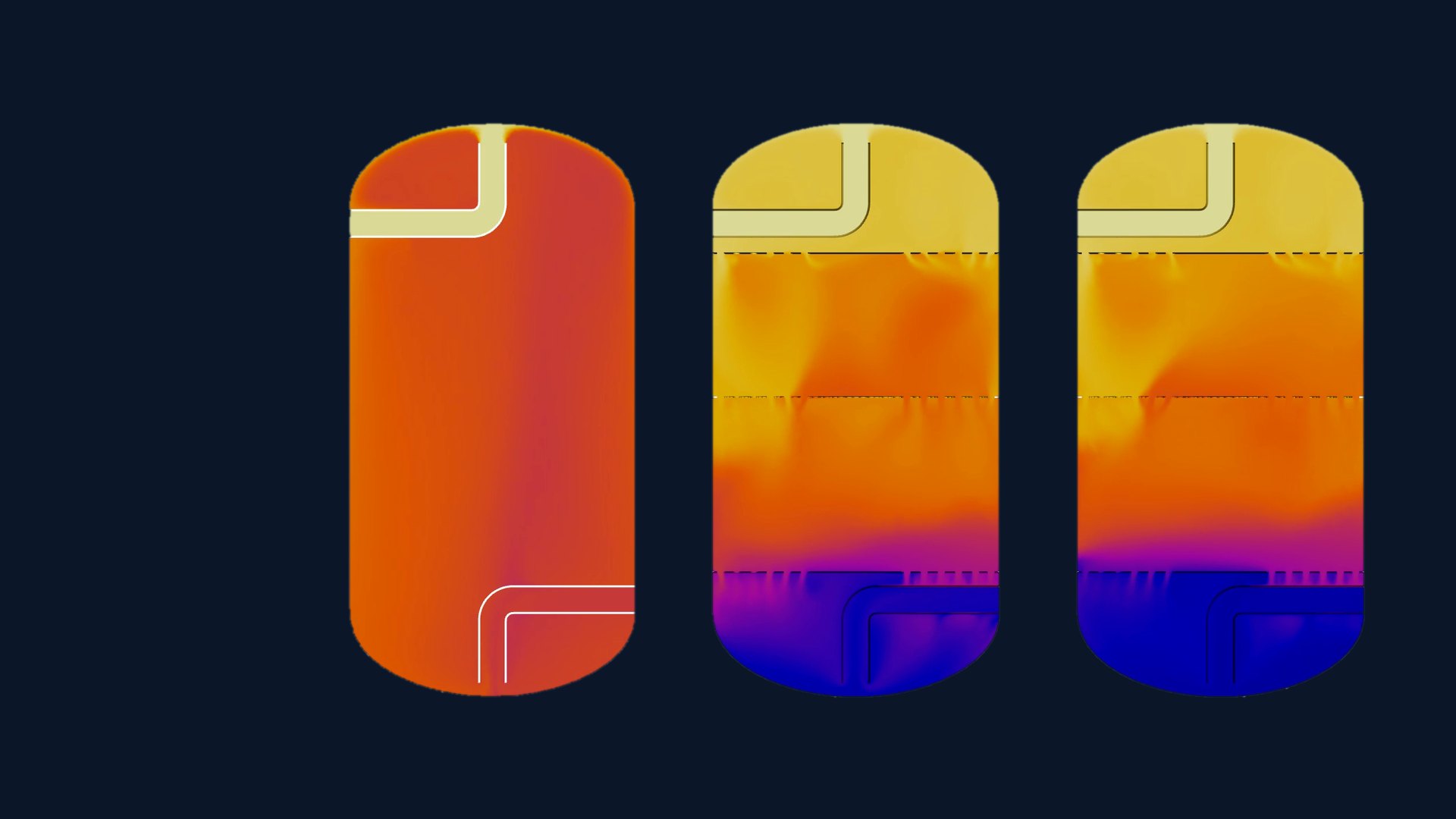
The same TES tank at the same discharge flow, stored at 20 °C (68 °F), modeled three ways: without baffles, with three perforated baffles, and with three perforated baffles and a 30 % glycol solution. Warm return water enters at the top and the outlet draws from the bottom. The videos cover the first 240 seconds of discharge, and the readouts mark when each outlet first rises 1 °F.
Without baffles, the outlet passes a 1 °F rise at 102 seconds. Three perforated baffles hold it until 182 seconds, and three baffles with 30 % glycol until 203 seconds, about twice as long as the open tank. At 240 seconds the outlet is 15.0 °F above the stored temperature without baffles, 6.4 °F with three baffles and 3.8 °F with glycol.
Outlet temperature vs time
Outlet temperature from the Fluent outlet monitor for each case, in °F with °C on the right, with the 1 °F rise (69 °F) and the second each case first exceeds it.
How a TES tank works in a data center
Stratified chilled water storage: the thermocline sets thermal ride-through time
A TES tank acts as a capacitor in the chilled water loop. The design question is how many seconds, at the specified flow, before the water leaving it warms past the limit.
Data centers commonly use thermal energy storage (TES) in the form of a large, vertical, stratified chilled-water tank. The tank backs up the main cooling system and smooths the plant's response to intermittent spikes in thermal load. Its most critical role is bridging the gap between a loss of normal cooling and full chiller plant recovery, which makes it the thermal equivalent of an electrical UPS.
The thermocline is the transition layer between the cold water and the warm water, where the water shifts from cold to hot. A well-designed TES tank keeps this layer as thin as possible by maintaining thermal stratification as the thermocline moves through the tank. Usable capacity depends on preserving that stratification. Mixing thickens the thermocline and shrinks the volume of water still at the required chilled-water temperature. A tank that mixes heavily can hold far less usable capacity than its volume and may carry the load for only a short time before supply water rises above the allowable temperature.
Scope of the analysis
What the TES tank CFD evaluates
Transient CFD models full discharge and recharge cycles at your design flow rates to verify thermal stratification, usable capacity and the required ride-through time. Where the design falls short, we propose design improvements and re-run the simulation to confirm they close the performance gap.
Outlet temperature and usable capacity
The outlet temperature, second by second, and the moment it crosses your allowable rise. That moment fixes the usable volume in gallons, which we compare with the volume the specification requires.
Perforated baffle plates
Number, elevation and open area of full-diameter perforated plates. A solid center stops the inlet jet from punching through, and the hole rings spread the flow across the tank. An added plate does not always help, so arrangements are compared directly.
Diffusers, nozzles and inlet conditions
Nozzle size, inlet velocity, risers and diffusers, each judged by the mixing it causes at the inlet. A ride-through tank turns over most of its volume in minutes, so inlet momentum decides how long it holds.
Tank geometry, aspect ratio and volume
Shell height, diameter and aspect ratio. A taller tank gives the thermocline a smaller share of its height. If the shell cannot meet the specification, the analysis shows how much more height or volume closes the gap.
Charging and recharge
The charge half-cycle after the chillers restart or after other load-shift events: how long the plant needs to restore the cold volume at its recharge flow, and whether a clean thermocline re-forms before the next event.
Vertical and horizontal tanks
Horizontal tanks fit where height is limited, but they de-stratify more easily because the layers must hold along the length of the tank. CFD shows how far they hold and which internals keep them apart.
Deliverables
What you receive
- Outlet temperature vs time, with the allowable-limit crossing marked
- Usable volume and usable capacity within the allowable rise, against the required volume
- Temperature cross-sections over time showing thermocline position, thickness and progression
- Velocity fields showing inlet jets, flow through each baffle and any short-circuit to the outlet
- A pass or fail against the specification, with the design changes that make it pass
- An engineering report with model setup, boundary conditions and results, ready for design review or a submittal, typically within a few days
Inputs
Analysis Data Inputs
- Tank dimensionsOD, shell height, heads, orientation
- Nozzlessize, elevation and orientation
- Internalsbaffles, diffusers, risers, dip pipes
- Flow ratesGPM during discharge and recharge
- Temperaturesstored and return, °F
- Specificationallowable rise and required duration
- Fluidwater, or glycol type and concentration
- DocumentsRFQ, spec section or submittal
Who we work with
For the teams that specify, build and commission TES tanks
We analyze new designs before fabrication and installed tanks that must prove their thermal ride-through.
Questions