Introduction
Mufflers are usually made of so-called two shell parts. This means that the upper and the lower side of the muffler are formed and later welded together. Mufflers are subjected to constant thermal and structural loading. Structural loading mainly comes in the form of exhaust pressure waves. These pressure waves have different frequencies and amplitudes. When mufflers are not designed appropriately, they can get into resonance with the pressure wave and this results in an undesired drone sound. It is therefore important to design the muffler in a way that the natural frequencies of the muffler would not align with the frequency of the pressure wave.
In this case study, sheet metal optimization is presented. The optimization algorithm adjusts the position of the shell finite elements, to obtain the optimal design.
Geometry and mesh
The sheet metal was meshed using shell finite elements.

Loads and Boundary conditions
The muffler is constrained on the lower edge of the sheet metal. the goal of the optimization was to increase the natural frequencies of the muffler. The manufacturing constraints were also considered.
Results
Initial model
We were initially interested in the natural frequencies of the muffler before optimization. The first four natural frequencies of the muffler are presented below.


Optimized shape
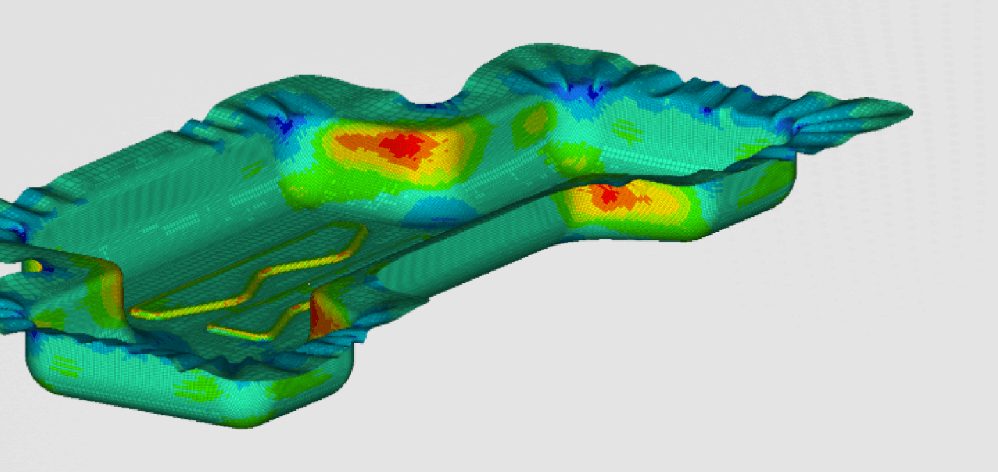
The optimized shape of the muffler can be seen in the figure 3.


It can be seen that the natural frequencies have in some cases increased by almost 250%. This is a huge advantage considering the fact that the weight stayed almost unchanged.